
How Xiamen Ruicheng took a six-component ABS cabinet housing through every stage of its production cycle, from the first DFM email to ship-ready cartons.
At a glance
- Client
- Industrial-equipment manufacturer (Russia)
- Supplier
- Xiamen Ruicheng Industrial Design Co., Ltd.
- Product
- 6-component ABS cabinet / chassis housing
- Cycle
- Communication, tooling, T1 sampling, revision, mass production, shipping
- Method
- Color-coded DFM, one engineering interface, deviations closed at sampling
- Outcome
- 500 ship-ready sets, 100% appearance inspection, zero cosmetic rework reaching volume
Most enclosure articles stop at the molding. This one does not. A six-part housing is not a single part with a quote, it is a chain of decisions that runs from the first email to the last carton on the truck. Miss one step and the failure shows up three stages later, usually right before the ship date. Below is the whole program Xiamen Ruicheng ran for a Russian industrial-equipment maker, phase by phase, using the drawings, tools, trial shots and change records from the program itself.
Pre-project communication: the DFM dialogue
Where the real risk was defined, before any steel was cut
The customer arrived with a complete 3D assembly, six parts that had to agree with one another as a single enclosure, and a surface-specification discipline sharper than most. Their DFM feedback was not a wish list, it was a set of working rules, and it shaped the entire program. In their own words, carried into the project as written requirements:
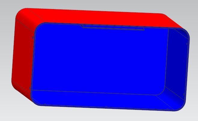
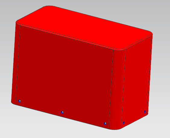
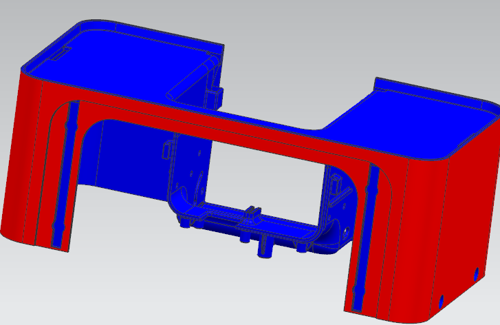
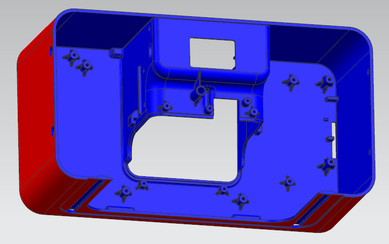
Use colour to distinguish the different surface-finish requirements.
Please also use colour to distinguish the surface requirements. Can the gate location be changed to the one shown below? Will this shrinkage be serious?
We need to see the internal molding detail of the tool: the core, the ejection system, the cooling layout. Can that be shown on the mold-design drawing?
This part must be made fully polished, no VDI-36.
This is the main part and it is an appearance surface. In production, please try to weaken the gate mark. (Can VDI-36 hide the gate scar?)
That last exchange is the whole thesis in miniature. The customer was not asking for a box, they were asking for a visible face that would not betray a gate scar. Xiamen Ruicheng answered it by locking one drawing convention before tooling:
Quotation and tooling: six parts become six molds
What the quotation, mold design and the tools themselves actually show
The assembly resolved into six components, each quoted as its own mold. The shared baseline was consistent: an S50C mold base, P20 core and cavity, a single cavity per tool (1x1), and ABS in black. What changed per part was the surface map, and that is exactly where the earlier dialogue paid off. The part codes below are the ones stamped on the tools, so the article, the drawing and the mold all use the same names.
| Part (code on the mold) | Mold base / core | Cavity | Material | Surface requirement (agreed at DFM) |
|---|---|---|---|---|
| Case 1 (CASE1) | S50C / P20 | 1x1 | ABS, black | Internal polished + external VDI-36 |
| Base (CASE2) | S50C / P20 | 1x1 | ABS, black | Internal polished + external VDI-36 |
| Conduit (PIPE) | S50C / P20 | 1x1 | ABS, black | Internal polished + external fine matte |
| Door (DOOR) | S50C / P20 | 1x1 | ABS, black | Internal polished + external VDI-36 |
| Door panel (DOOR-PANEL) | S50C / P20 | 1x1 | ABS, black | Fully mirror-polished, no texture |
| Top case (TOP_CASE) | S50C / P20 | 1x1 | ABS, black | External VDI-36 body, mirror-polished front appearance face |
Mold design ran as 3D STEP models before any steel was cut: the parting line was fixed, every face was checked for release, and the red/blue surface map was carried into the tool itself. The customer's question about gate position and shrinkage on the thinner walls was answered on these drawings, not discovered on parts.
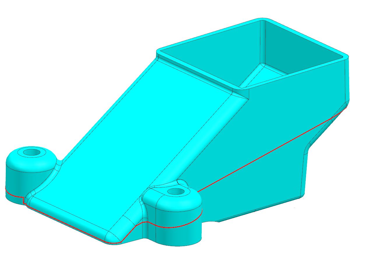
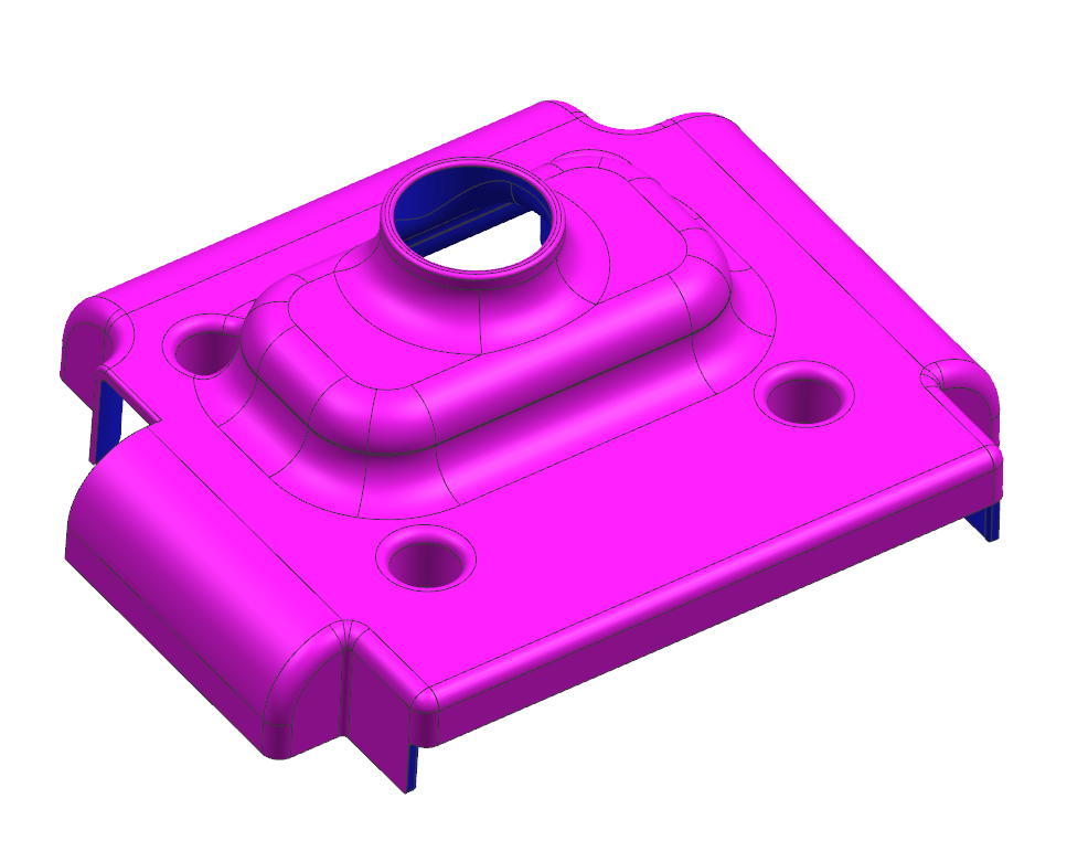
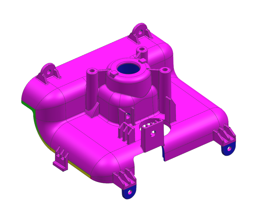
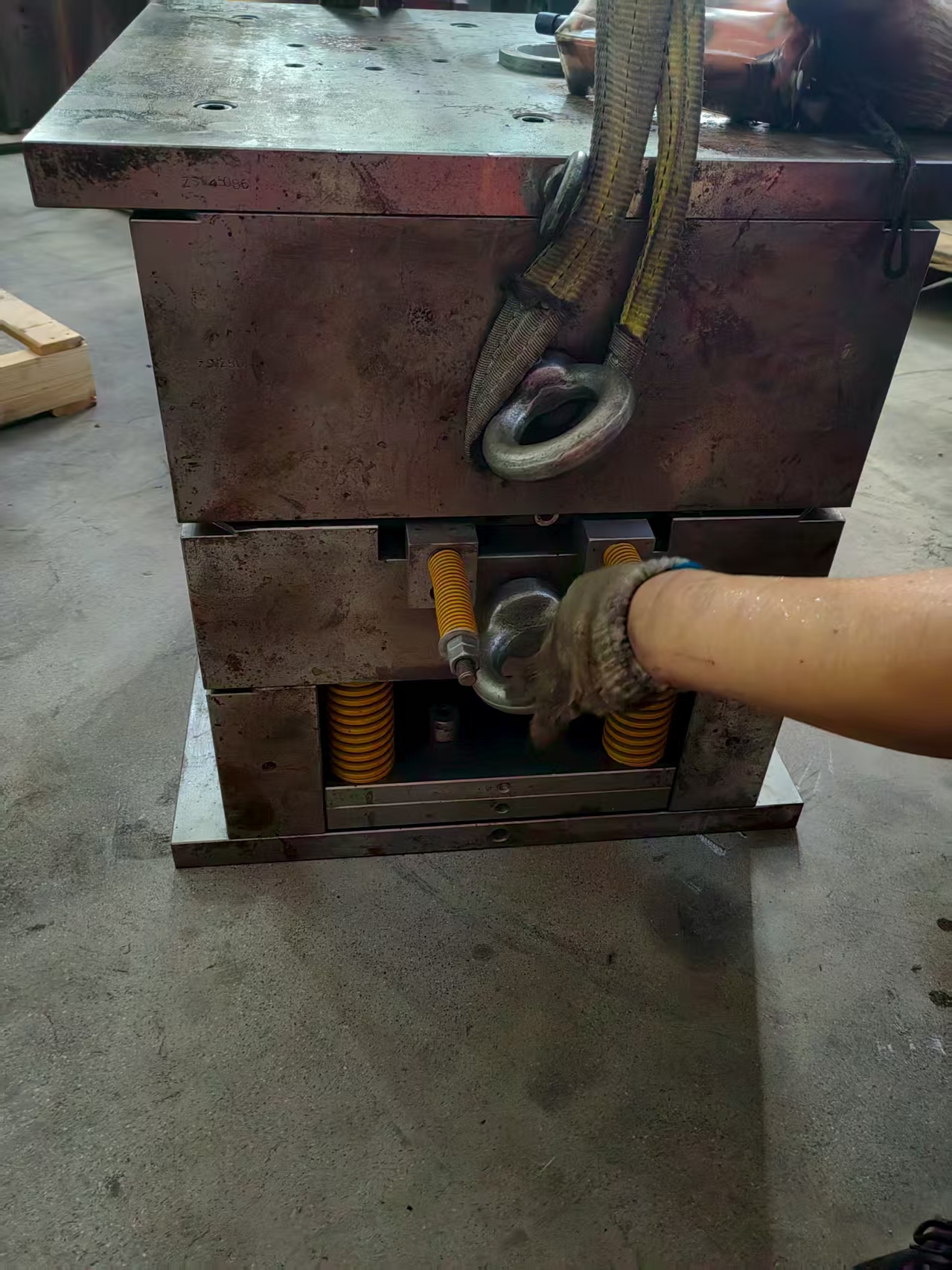
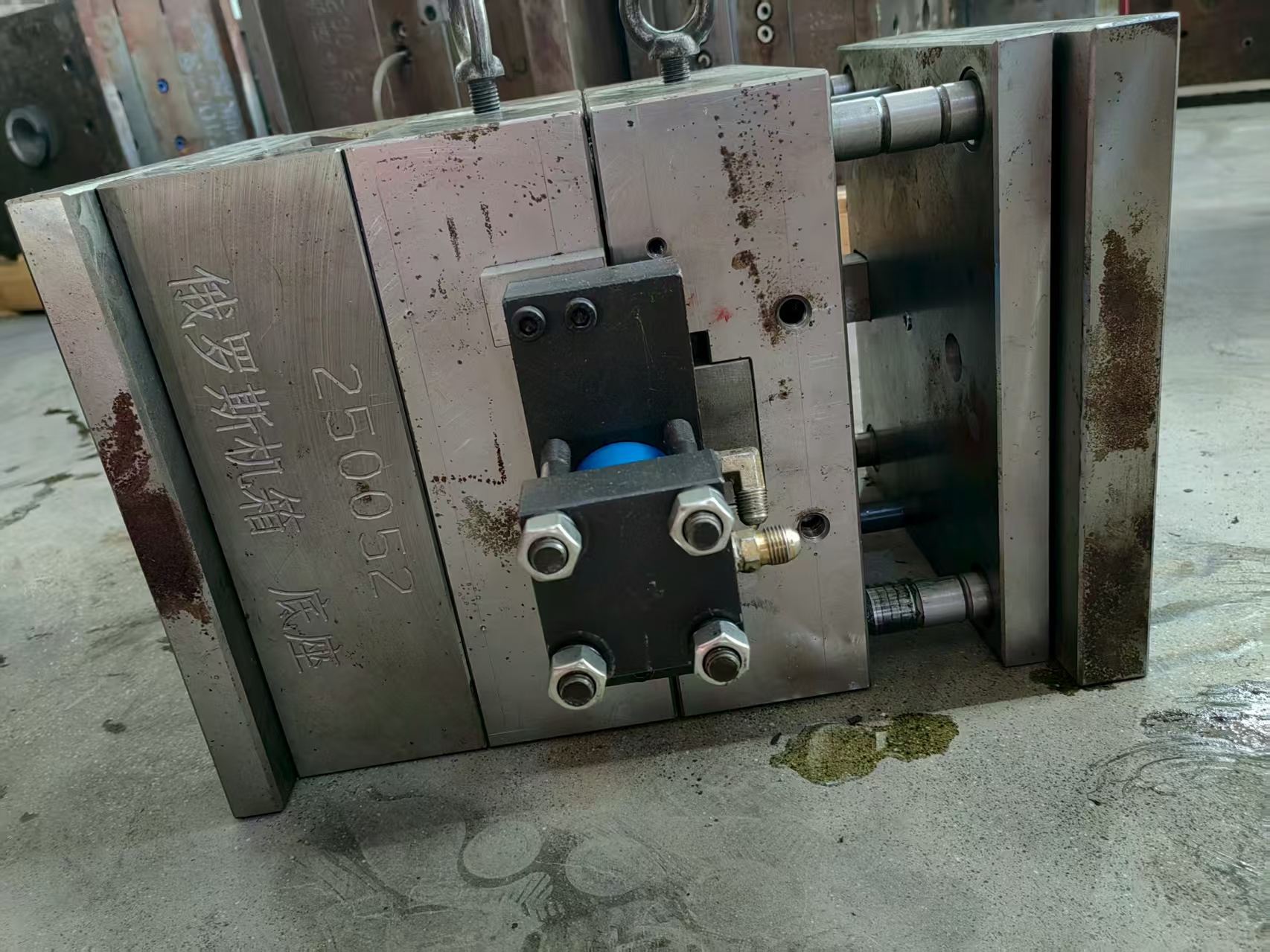
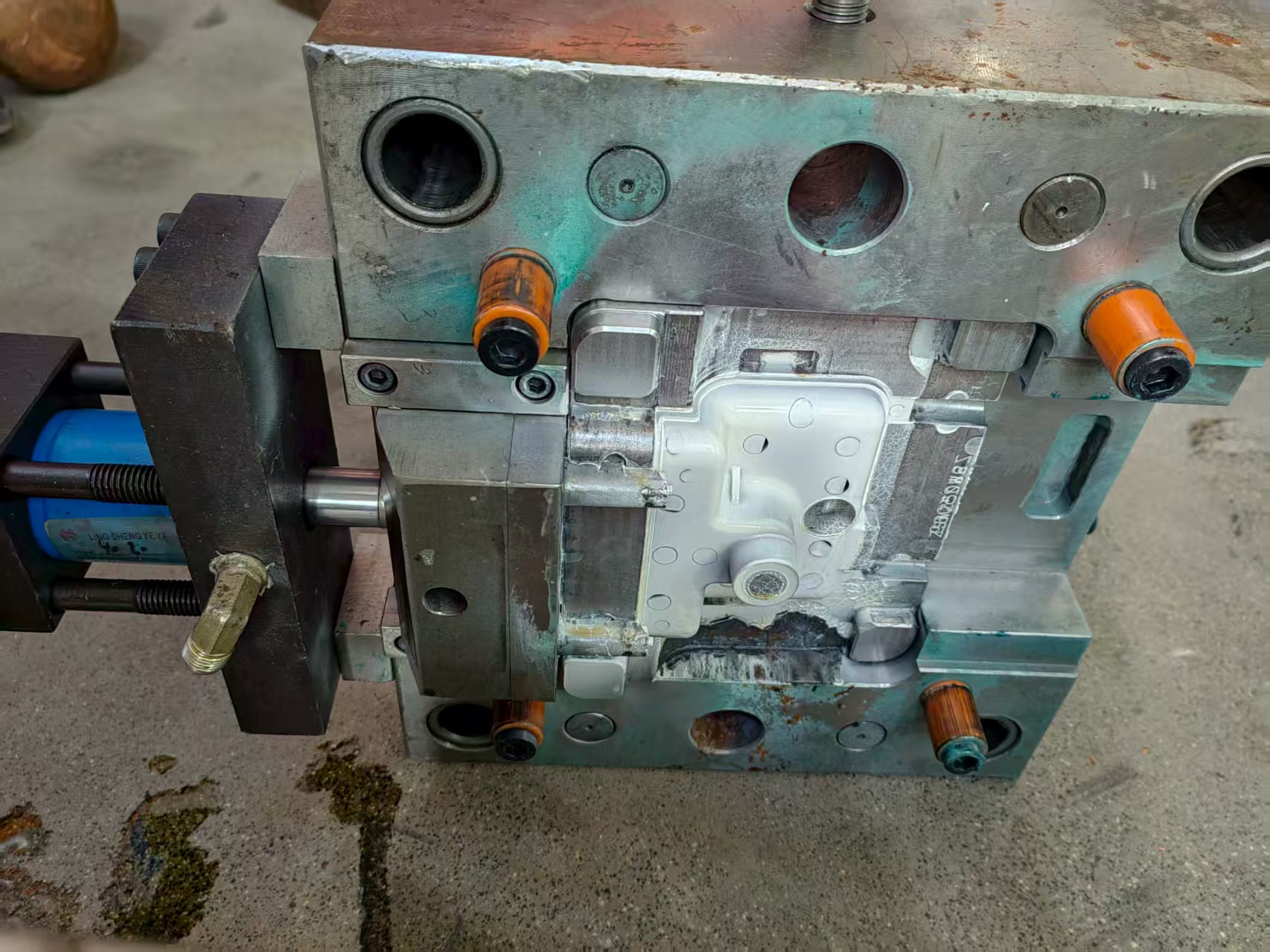
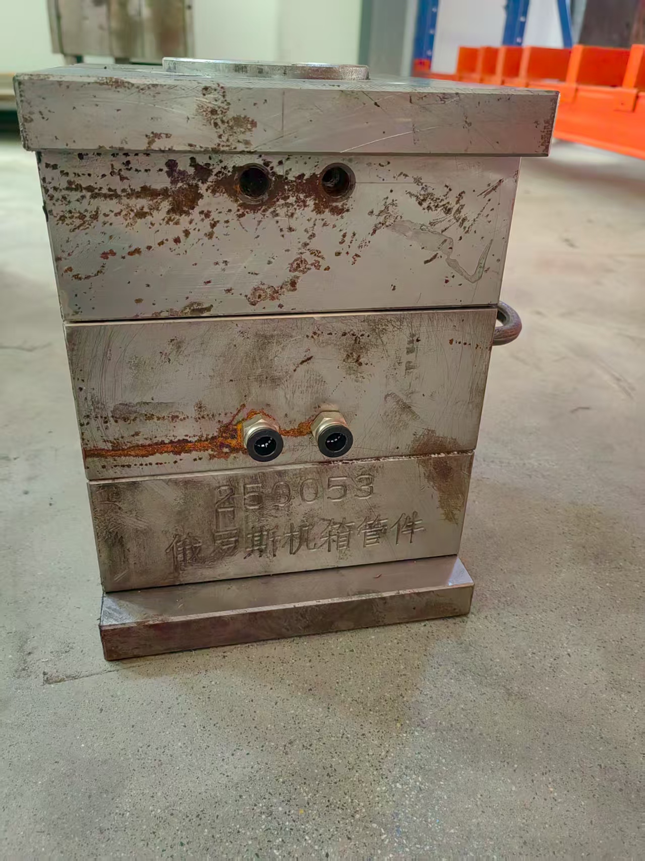
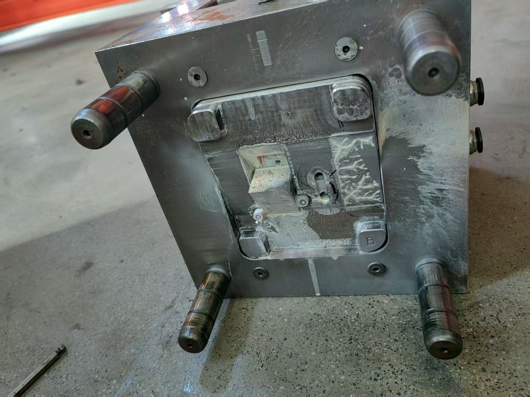
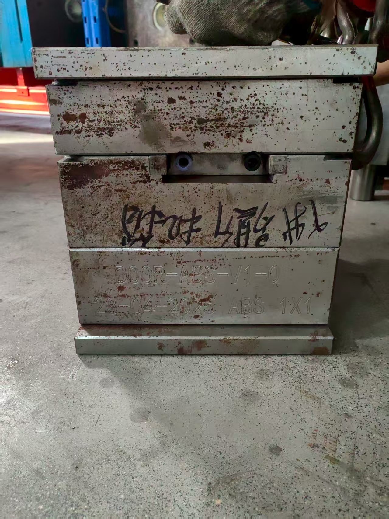
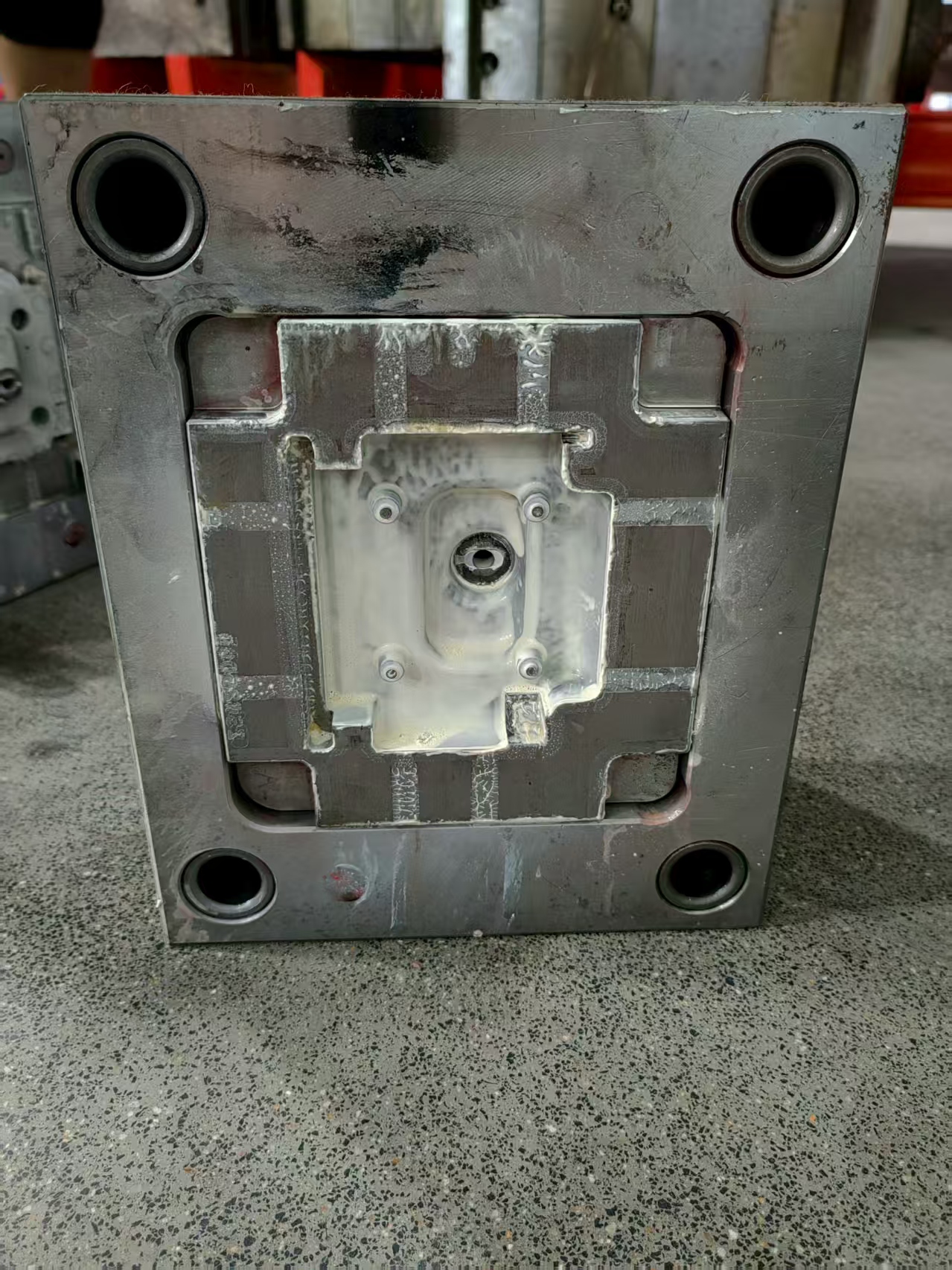
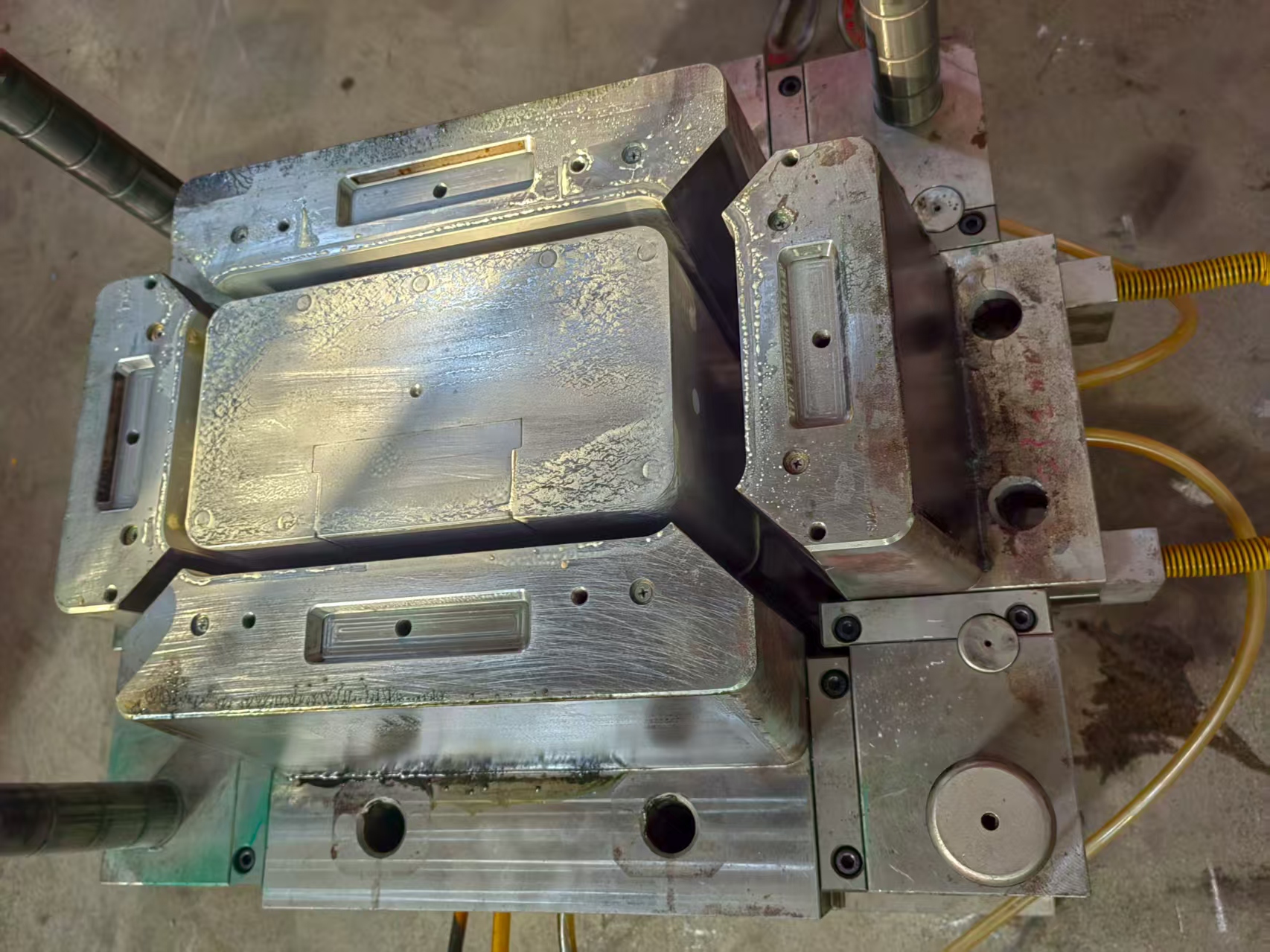
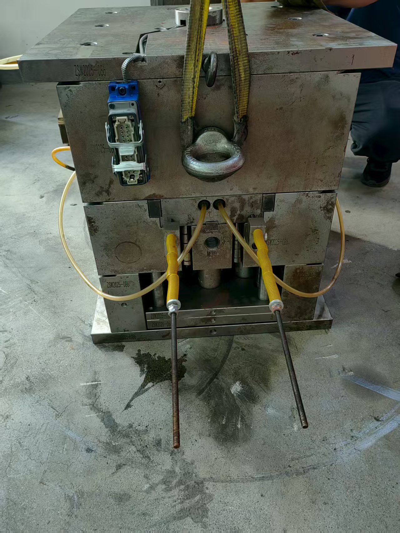
The six tools, as built
What follows is the tooling record itself. These are photographs of the steel molds, not studio renders: mold bases, cavities, guide pillars, slides and ejector springs, with each tool stamped with its own part code. On a six-part program you are not buying one mold, you are buying six that all have to hold the same surface language.
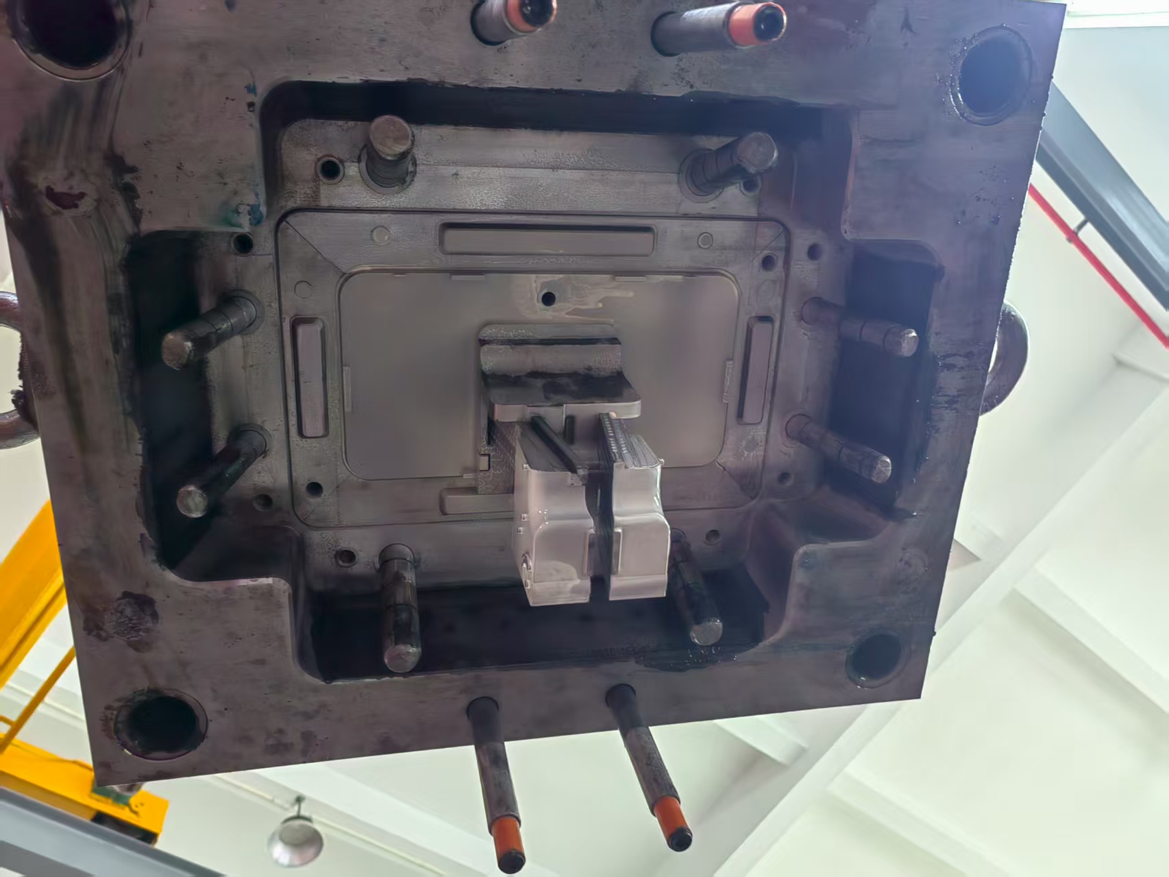
How the six parts become one enclosure
The six tools above each make one part. Together they build the enclosure carried through the rest of this program — a housing whose six components had to agree on surface finish and fit before it could function as one product. With the tooling proven, the next step is committing all six parts to a single production dispatch.
Production dispatch: the formal kickoff
One project name, six parts, a sample deadline and three flagged revisions
A formal production dispatch was issued to lock the program: one project name used identically across every mold, revision and production order, six parts listed with their mold base, core, cavity, material and surface requirement, and a hard internal deadline to deliver sample sets by late July. Three of the six parts were already flagged in the dispatch as needing mold revision, so the engineering team went in knowing where to look rather than finding out at first article.
What the dispatch fixed before production started
- SpecSingle project naming across mold, revision and mass-production orders, so no part could drift under a different label.
- SpecEvery part's surface map written into the order (internal polished + external VDI-36; conduit external fine matte; door panel fully polished).
- DeadlineSample sets due by late July, driving the whole sampling schedule.
- Pre-flagThree parts pre-marked for mold revision, so the T1 review had a known target list.
The value of the dispatch is not paperwork. It is that the surface map and the part codes were fixed in one document before the tools ran, so a T1 finding could be traced straight back to a requirement instead of an argument about what the drawing meant.
T1 first-article review: where it nearly went wrong
Three real deviations caught at sampling, not in volume
This is the phase that decides whether a program ships clean or slips. The T1 samples were compared part-by-part to the 3D model and the surface map. A drawing can never show what a sample reveals, and on this program the sample revealed three things.
T1 deviations found and root-caused
- DefectTwo ribs unequal. The model calls for two identical ribs; the sample came out with a step between them. Root-caused against the model and corrected before mass production.
- DefectThin-wall void. A thin-wall zone tended to form an unwanted void that the drawing did not show. Resolved by a controlled add-material decision taken with the customer's engineering lead before any mold correction.
- DefectReversed A/B faces. The original part definition had the A and B faces swapped, which dropped the ejector pins onto a visible surface. Contained to a validated paint step rather than a mold re-cut.
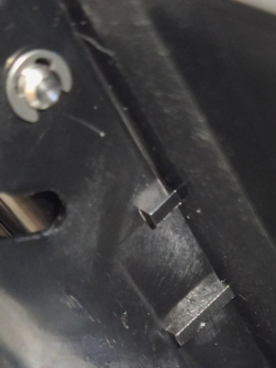
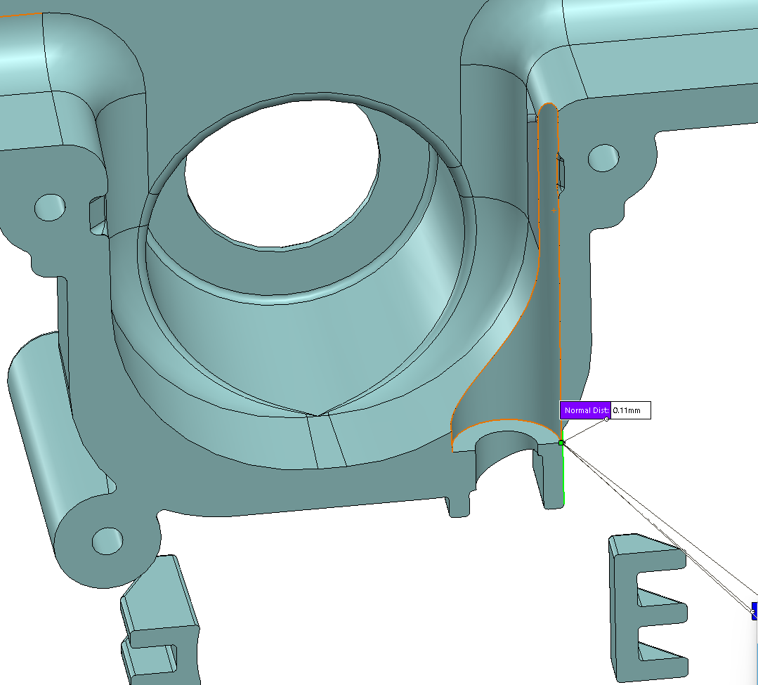
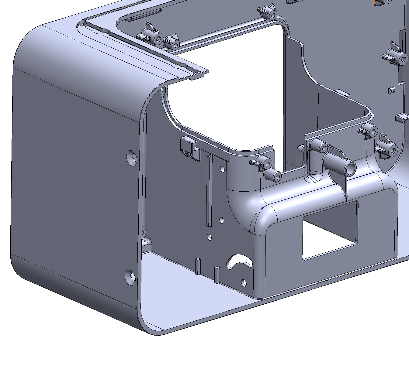
The reversed-face issue is the one worth sitting with. It originated in the part definition, not the tool, which means the only safe fix is a validated surface treatment on the now-visible face, confirmed on samples, not a silent mold change. That discipline is what kept the program from a late, deadline-breaking re-cut.
Trial runs, straight from the press
The clips below are the tools running on the machine during sampling, five of the six parts. There is no clip for the door because none was recorded; the stills of that tool stand in for it. These are the moments a part is first pulled, which is why the T1 review is tied to them.
CASE1 Case 1, trial run
The CASE1 tool cycling: the press closes, injects, opens and ejects the part.
CASE2 Base, trial run
The base tool running. The side core-pull is the extra motion on this one.
PIPE Conduit, trial run
The conduit tool cycling. The outside finish is the part of this shot worth watching.
TOP_CASE Top case, trial run
The top-case tool, the appearance part, running its first shots.
DOOR-PANEL Door panel, trial run
The door-panel tool. This is the fully polished part, so every shot is checked for surface.
Design change and revision: closing the loop on samples
Every correction built as a sample, confirmed, then released
Late in the program a consolidated change round folded the T1 findings and new feedback into one reviewed package. Nothing was applied to volume unverified. Three concrete change items were sampled and confirmed with the customer.
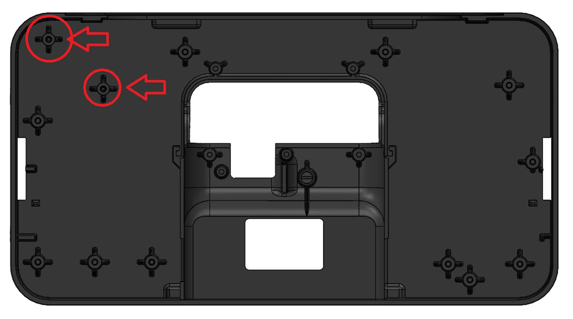
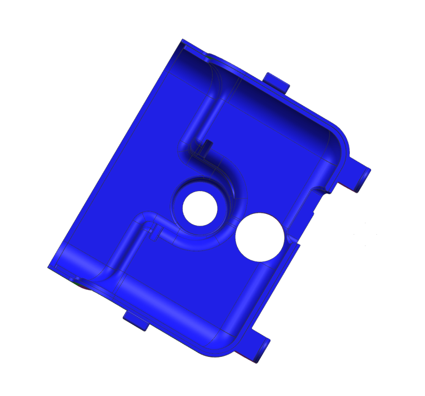
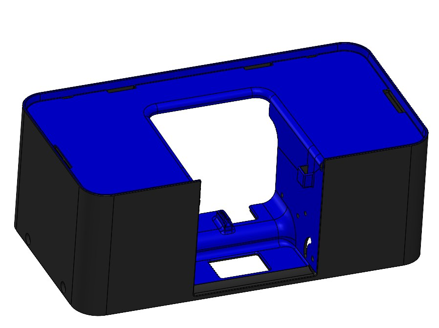
Change items, sampled and confirmed
- FixColumn height. Two bosses reduced by 3 mm while holding internal and external diameters, so assembly fit was unchanged.
- FixVisible-face pin marks. Painting options built as samples and selected on real parts, avoiding a mold re-cut.
- FixTransit abrasion. Early shipment photos showed top-surface scuffing because the bags did not fully cover the parts. The fix: larger bags for full coverage, foam bags above the relevant order volume, and individual boxes per part.
- Process100% inspection. Full appearance inspection written into the mass-production gate.
Mass production: 500 sets, inspected at the gate
Repeat the validated parts, verify every one
With the tooling corrected and every change confirmed on samples, the program entered mass production for 500 sets. The surface maps that started as colour-coded drawings now governed the floor: each part ran to its agreed red/blue finish, and 100% appearance inspection sat at the production gate rather than as a final spot-check. Because the deviations had been closed at T1, the inspection step verified conformance instead of discovering surprises.
The same six tools that had been photographed open and closed during tooling now ran the volume. Nothing about the part changed between T1 and the run except the corrections already confirmed on samples, which is the whole point of closing deviations at first article.
Packaging and shipping: the last failure mode
Cartons, shipping marks and the pre-holiday window
The enclosure left the building only after the packaging spec was locked from the transit-abrasion lesson: each part in its own individual box, larger bags giving full coverage, foam bags above the relevant volume, and shipping marks carrying both quantity and part number so the customer could receive and sort without opening every carton. The whole order was sequenced to ship 500 sets ahead of the Chinese New Year holiday, which meant the production order had to be confirmed before year-end to protect the window.
What actually shipped
Stated as outcomes rather than capability lists, because outcomes are what a buyer is really weighing:
- The T1 deviations, the unequal rib and the thin-wall void, were closed at the sampling stage, so no cosmetic rework loop carried into mass production.
- The reversed-face issue was contained to a validated paint step, not a mold re-cut, and confirmed on samples the customer selected.
- The packaging change removed the transit-abrasion failure mode seen in the first shipment photos.
- 100% appearance inspection was in place at the mass-production gate.
- The program met a fixed pre-holiday ship date under one engineering interface, instead of slipping across three vendor hand-offs.
Frequently asked questions
What does a full end-to-end enclosure program actually include?
Far more than the molding. For a six-part ABS housing the program runs from the first DFM dialogue with the customer, through quotation and tooling, a formal production dispatch, T1 first-article review, design change and revision, mass production with 100% inspection, and finally packaging and shipping. Each stage hands a resolved requirement to the next, so failures are caught early rather than in volume.
What happens in the pre-sales communication or DFM dialogue?
The customer shares 3D drawings and surface-finish expectations. In this program that meant colour-coding every face (red VDI-36 texture, blue mirror polish), confirming gate position and shrinkage on thin walls, and agreeing the appearance-critical parts. Locking these on the drawing before steel is what prevents the rework loop.
What is the real risk in a multi-part injection-molded assembly?
Not the molding itself, but the coordination. When a housing is several parts that must agree on surface finish and fit, failures appear at the seams: a polished face that comes out textured, a rib off the model, ejector marks on a visible surface. These are designed out by deciding surface requirements at the drawing stage and closing deviations at first-article review.
What does a T1 or first-article review actually catch?
It catches what a drawing cannot: a rib that comes out unequal to its twin, a thin-wall zone that wants to void, and a part whose A and B faces were defined swapped, putting ejector pins on a visible surface. Each is root-caused at sampling, not patched in mass production.
How are ejector-pin marks or reversed faces handled on visible surfaces?
Options include repositioning the gate, a light surface texture to mask the mark, or a validated painting step on the polished face. The choice is built as samples for the customer to select before mass production, so no change reaches volume unverified.
Can one supplier own DFM, tooling, sampling and inspection for a six-part assembly?
Yes. Coordinating a multi-part injection-molded assembly under Xiamen Ruicheng's single engineering interface, rather than handing off between a mold shop, a sampler and an inspector, is what keeps surface requirements and deviations resolved without the rework loop that normally hits complex housings in mass production.
Need a multi-part ABS housing taken from RFQ to ship-ready?
Xiamen Ruicheng Industrial Design Co., Ltd. handles DFM, tooling, sampling, revision, mass production and shipping under one roof.
Start a project conversation with our engineering team, or browse more injection-molding case studies.
Post time: Oct-27-2026